The hand throttle position sensor on JCB 3CX, 4CX, and 5CX backhoe loaders plays a critical role in determining the throttle position set by the operator. This guide outlines the sensor’s function, position, signal characteristics, and the testing procedure for maintenance.
Related Contents:
2024 JCB ServiceMaster 4 v24.6.2 Free Download for Win 10 Win11
JCB Heavy Duty Truck Diagnostic JCB Electronic Service tool
JCB ServiceMaster 4 V24.06 Diagnostic Software
Function
- The hand throttle position sensor detects the position of the hand throttle, providing a signal to the engine control unit (ECU) to regulate engine speed based on operator input.
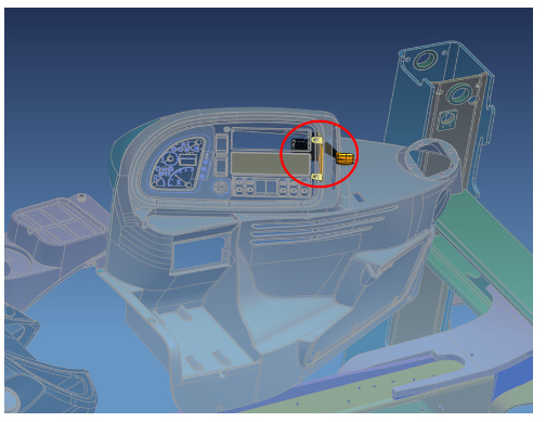
Location
- On JCB backhoe loaders, the hand throttle position sensor is mounted under the front console.
Signal Characteristics
- The sensor outputs an analogue voltage ranging from 0 to 5 volts.
- The voltage output is proportional to the throttle position.
- The sensor includes two accelerator pedal tracks to ensure safety in case of accelerator pedal failure.
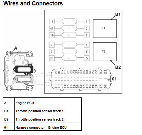
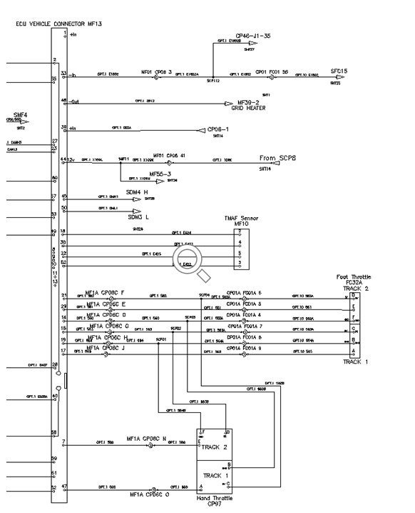
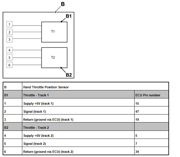
Interior Electrical Diagram
- The electrical connections of the sensor involve specific pins that relate to the power supply, ground, and signal output, ensuring proper functionality and communication with the ECU.
Testing Procedure
Important Note:
- When testing the sensor, use a multimeter on the wiring harness connector pins. Do not use a gauge on the ECU pins, as this could cause damage (Refer to SN0011).
Steps:
- Disconnect the Sensor:
- Disconnect the wiring harness from the hand throttle position sensor.
- Turn the Ignition On:
- Turn on the vehicle’s ignition to supply power to the sensor.
- Check Supply Voltage:
- Use a multimeter to measure the supply voltage at the connector pins.
- Pins 1 and 4: Should show a voltage of 5 volts.
- Pins 3 and 6: Should be at ground (0 volts).
- If Voltage is Incorrect:
- Check the wiring harness for continuity and proper grounding.
- Inspect the ECU pins for any signs of dirt or corrosion that could affect the connection.
- Use a multimeter to measure the supply voltage at the connector pins.
- Measure Signal Voltage at Throttle Idle:
- With the throttle in the idle position, measure the signal voltage:
- Pin 2: Should read between 1.0 to 1.2 volts.
- Pin 5: Should read between 0.4 to 0.6 volts.
- With the throttle in the idle position, measure the signal voltage:
- Measure Signal Voltage at Full Throttle:
- Fully depress the throttle and measure the signal voltage:
- Pin 2: Should read between 4.0 to 4.5 volts.
- Pin 5: Should read between 2.2 to 2.5 volts.
- Fully depress the throttle and measure the signal voltage:
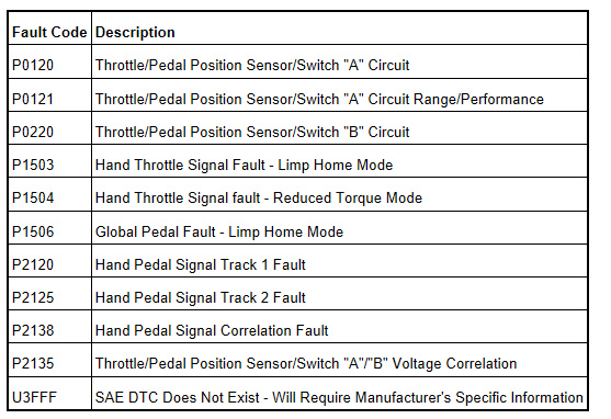
Related Error Codes
More repair case for JCB,please refer to:JCB Trouble Repair