Have you ever had an ECM connection issue? No communication, no flashing, or no configuration? This article will guide you through ECM flashing and basic configuration of select Caterpillar ECMs. We will cover the basics of flashing A2, A3, and A4 ECMs, including application software installation and configuration required for a successful setup. Topics include duplicating configurations, flashing preparation, flashing procedures, and basic configuration.
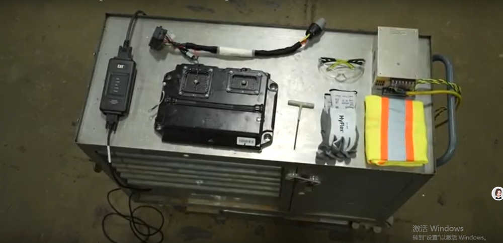
Before you begin, always follow safety protocols and prioritize safety. Let’s get started with preparation. If performing flashing and configuration on a test bench, you will need the Caterpillar Communication Adapter 3 (Part Number 538-5533), software, and power supply. Make sure you use the correct wiring harness for your ECM and machine, as using an incorrect harness can cause permanent ECM damage and may void your warranty.
For further guidance, refer to the Operation and Maintenance Manual or contact your local Cat dealer. Important reminders before you begin:
1. Keep all parts clean to prevent contamination, which can cause premature wear and shorten component life.
2. Ensure there are no electrical anomalies in the system or workbench.
3. Use only official Caterpillar tools and authorized software to prevent communication and flashing issues. Using unofficial tools may void your warranty.
This tutorial will use a rebuilt A4 E4 10R 5648 engine ECM, configuring it for a 140 motor grader.
Section 1: Copying a Configuration
Copying a configuration is useful when replacing an ECM to transfer settings from the old ECM to the new ECM to reduce setup time.
Step 1: Connect the Cat Communication Adapter to the laptop.
Step 2: Connect the adapter to the ECM. If installed on the machine, ensure the connections are correct. For test bench flashing, ensure the ECM, adapter, and bypass harness are properly connected to the power source. Power up the machine or start the power source (12-32 VDC) as needed.

Step 2 (continued): Launch Caterpillar Electronic Technician (Cat ET) and select the ECM from the available list. If the previous ECM was faulty, avoid using the Copy Configuration function because corrupted data may be transferred to the new ECM. If the ECM exhibits erratic behavior, fails to communicate, or fails to retain parameters, skip to Step 4.
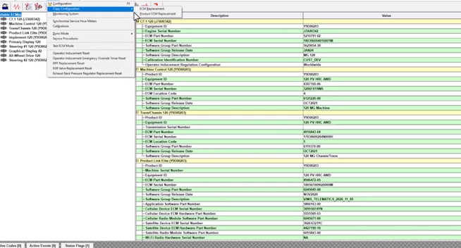
Step 3: Use the Copy Configuration ECM Replacement function in Cat ET. Load the information from the ECM and click Yes. When the process is complete, save the file to disk.
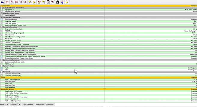
Step 4: If you are not already on the configuration screen, select the toolbar button or press F5 to launch it. Select Print to File to generate a PDF documenting all parameters.

Step 5: Create a Product Status Report for the ECM and save it as a PDF.
Step 6: Click the Disconnect button or press F8 to disconnect the ECM from Cat ET. Turn off power to the ECM.
Step 7: If installed on the machine, remove the ECM.
Step 8: Install a replacement ECM or prepare for bench testing.
Section 2: Prepare to Flash
Step 1: Follow the connection procedure in Section 1.
Step 2: Contact your Caterpillar dealer to obtain the correct flash file.
Step 3: Verify that the flash file (FLS or .fls2) is correct for your machine. Using an incorrect file may damage the engine and void the warranty.
Section 3: Flash the ECM
Step 1: Start Cat ET. If the ECM detection does not start, manually navigate to Utilities > WinFlash.
Step 2: Select the ECM to flash.
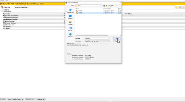
Step 3: Click the folder icon next to the Flash File field to locate the correct flash file.
Step 4: Verify that the information displayed matches your machine. Click Open.
Step 5: Click Start Flash.
Step 6: Monitor the progress bar until 100% complete. Do not interrupt the flash process as this may corrupt the ECM memory.
Section 4: Basic Configuration
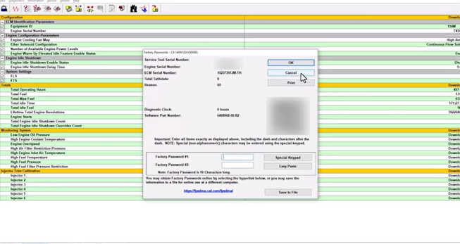
Step 1: If necessary, use Cat ET to enter the factory password to clear the rating interlocks. Activating the Test ECM mode will also clear the rating interlocks, but only on Tier 4 machines.
Step 2: Use Cat ET to program the parameters in Section 1, either by copying the configuration file or entering them manually. A factory password may be required.
Step 3: Check logged diagnostic codes and clear them as needed.