Here’s how to reprogram your odometer after an instrument cluster swap. The vehicle this was demonstrated on is a 2004 Honda Accord.
Step 1: Introduction
Odometer information is stored on a small EEPROM chip on the circuit board. The chip can be read and written to using a serial programmer. The information is coded in HEX characters. The odometer information can be copied over from the old cluster to the new cluster using Honda HDS, assuming the original cluster is operable. What follows is a hack-around to using HDS, by programming the mileage directly to the chip. You can also opt to merely swap the chips, or copy and paste the program, rather than decode.
Tools and Parts Required:
• Screwdrivers
• Soldering iron, solder and a de-soldering pump
• Computer with Windows XP and serial port
• 8 pin DIP socket
• Serial programmer
– Breadboard
– Hookup wire
– Female serial port header
– 5V from computer power supply
– 4.7K ohm resistors
– 5V Zener diodes
o Wire strippers
• Serial programming software (PonyProg freeware)
• A spare instrument cluster in case you screw up
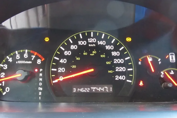
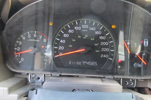
Here’s the original instrument cluster from my LX sedan, 314,622 km, and here’s my new cluster. It’s from an EX-L sedan with 211,150km.
Step 2: Disassemble the Instrument Cluster
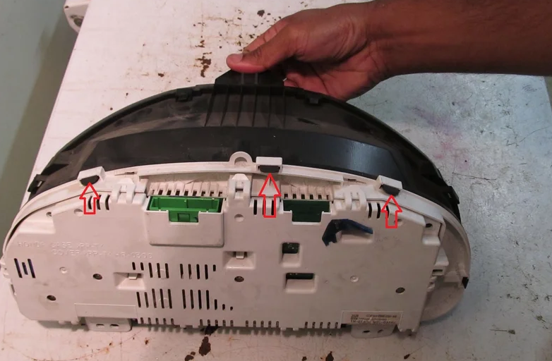
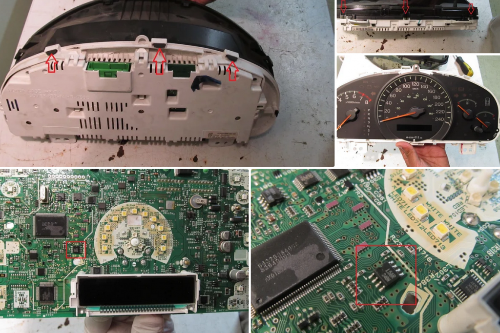
Once the cluster is out of the vehicle, pull up on a few tabs to remove the front plastic cover and fascia.
The needles will need to come off next. Pull up on them carefully and they’ll come out. Take a photo of their home position before taking this apart so you know where to realign it upon reassembly. Use gloves and don’t touch the black face of the gauges, it’s a fingerprint magnet.
Once the gauge face is removed, remove the white backing plate revealing the circuit board, with the L56 EEPROM chip.
Step 3: Solder Hookup Wires
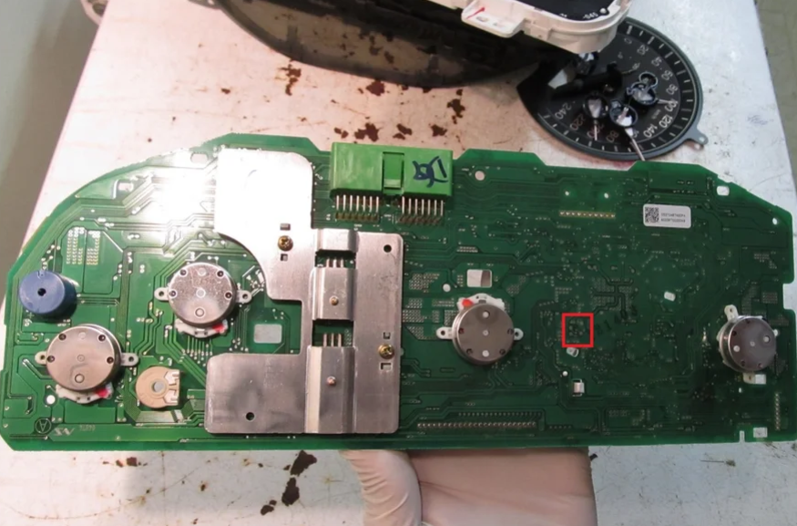
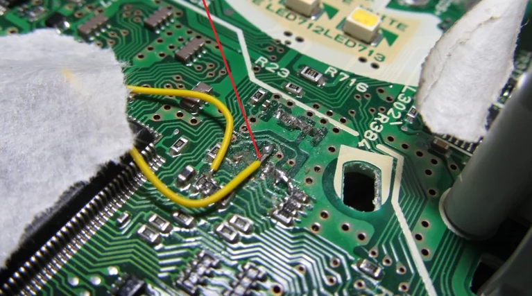
According to the datasheet, pins 1, 2, 3, 4, 5 and 8 will need to be connected for programming. To read the information off the chip, while it’s still in the cluster, we need to solder some hookup wires to the leads. If you use a multimeter you can trace the leads to the pads on the other side of the circuit board, and then solder some hookup wire.
Now before you can properly read from the chip, on board, you have to short the crystal, located to the top left of the EEPROM chip.
Step 4: Programming Hardware Setup
This is the EEPROM programmer I built to connect the chip to my desktop computer. It interfaces through the RS232 serial port. All it is are three 5V zener diodes ($1) and three 4.7K ohm resistors ($1). The rest is some 22 AWG hookup wire and a breadboard ($5). That’s it!
And here’s my programmer connected to the PC.
And the breadboard with the resistors and diodes.
Now here’s where it got tricky. Using the PonyProg software,
I was able to read and save the information from the odometer chip. But I wasn’t able to write to the chip. The EEPROM must be removed from the board if you want to write to it, as it can’t be programmed in circuit.
So off we went trying to desolder an SMD chip…
And SNAP!!! The leads broke off the chip. This is why you should use a hot air station so it heats all the pads evenly and you can just pick the chip off the board instead of prying it.
Luckily, I had saved the EEPROM information I downloaded earlier. I found another replacement chip, the Microwire 93C56 chip from a car’s ECU I had laying around. The 93C56 chip is identical electronically to the L56 chip.
So I soldered wires to the “new” chip, and was able to
connect it to the programmer directly, without having the board hamper the write function. The additional advantage is I could now quickly disconnect and reconnect my chip to the odometer board, and then test my new program out on the car as I decoded the odometer program.
Step 5: Programming: Reading From the EEPROM
I used PonyProg software, which is a free serial device programmer. It reads and writes to the COM port, which in my case is directly to the chip. If you don’t have a serial port on your computer, you can purchase an EEPROM programmer that connects via USB and emulates a serial port.
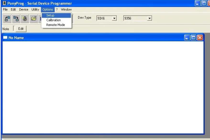
First thing, head over to the setup menu under options;
Make sure its set to read from the serial port, COM1, and SI Prog I/O. You can then Probe the port to make sure it detects your serial programmer.
Next head over to the device menu and select Microwire 93C56, which is compatible with the L56 EEPROM chip.
Then click Device –> Read to read from the chip. The information from the chip will be downloaded in HEX format in a 16 by 16 bit array.
Step 6: Decoding the Odometer Dump
At this point you can merely save the odometer dump, and
write it to your new cluster. Or if the engineer inside you is itching to make sense of 256 HEX characters, you can attempt to decode it.
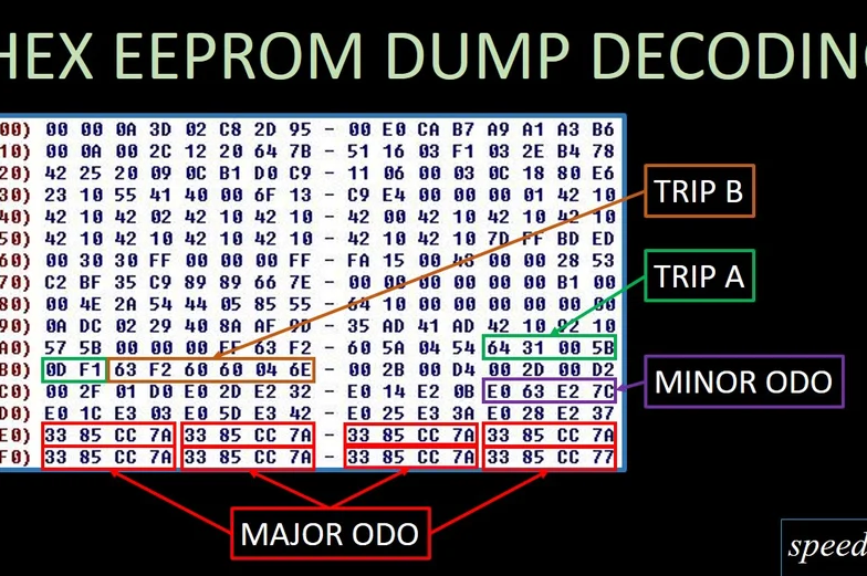
Here’s a look at the HEX dump. Through a lot of trial and error, back and forth in the vehicle, and a few hours of hair pulling, calculating and note-taking, I was able to come up with a rough idea of how the odometer program works.
The odometer has a major value in addition to a minor value that increments. Trip A and B are also stored in the EEPROM. The major value is what I’ll be focusing on, since that controls the thousands of kilometers which is more important.
Knowing this, if we focus on the last few lines in the EEPROM dump, you’ll notice the characters 33 85 CC 7A repeated 8 times. This is the major odometer value in HEX. The numbers are actually the HEX invert of each other, and act like a checksum. A HEX lookup table, which is 0-F and F-0 backward is used to determine the inverse of each character.
For example, a “3” will be inverted as “C”, and 8” inverted as “7” and “5” inverted as “A”.
Therefore the only characters that store actual information are the first two HEX digits, 33 and 85.
To decode, simply convert the number to decimal using a hex to decimal converter, and then multiply by 16 to give you the odometer reading in kilometers. I got 211,024km.
Using this method of calculation, I need the new cluster to read 314K, so I can divide it by 16 and convert it to HEX to give me the base value in the odometer dump. This value, 4C CF will then have a checksum of B3 30, which I will write to the chip.
Now I know it’s not exactly accurate but close enough, because there is a minor incremental value that I haven’t decoded. I made an excel sheet to help me convert the numbers.
Step 7: Writing Information to the EEPROM Chip
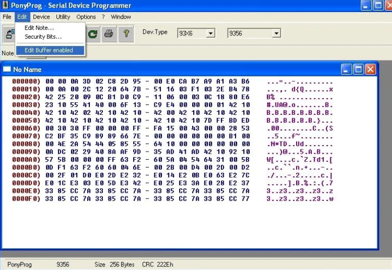
Now that we’ve got the corrected mileage value, head back to the PonyProg software and click Edit – Edit Buffer Enabled to enable writing to the HEX bits.
Click on the bit you want to edit and type in the new value. In my case I replaced all “33 85 CC 7A” with “4C CF B3 30”.
Here’s what my modified odometer dump looks like with the bottom two rows edited for 314K.
And that’s it, you can now disconnect the EEPROM from the programmer and hook it up to the odometer board to test it out.
Step 8: Prototyping
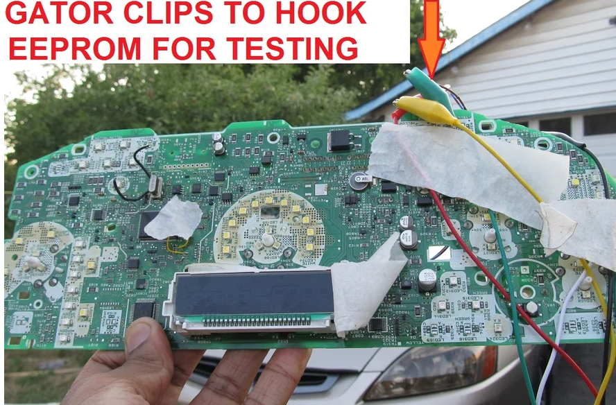
Since I still had the hookup wire attached to the original odometer board, I use it to temporarily connect the EEPROM chip with the 314K program on it and test it in the car to see if it works.
I used alligator clips to connect the six hookup wires to the EEPROM. It looks ghetto, but this is only a test before re-soldering the chip!
And start it up and it reads 314,543km, which is close enough to what I had on the old cluster.
I’ve also gained the outside temperature display option on the EX-L cluster.
Step 9: Closing Everything Back Up
Next, we can transfer the new programmed chip back onto the odometer board. In my case it was already soldered onto an ECU board, and it needed to be de-soldered. A hot air station is highly recommend here, as we broke more pins taking this one off too!
Then solder the new chip back onto the board.
When removing the original chip, a few of the pads got damaged. Thus a patch wire was soldered in to compensate for the lack of conductivity with the board beneath the lead.
Now its time to reassemble the instrument cluster. Reinstall the needles, in the position that they originally
came off in. They have a stopper that has to be adjusted. Good idea to refer to a photo of the cluster before you took things apart to get it aligned.
Step 10: Results
Once everything is back together, connect it to the vehicle and start it up!
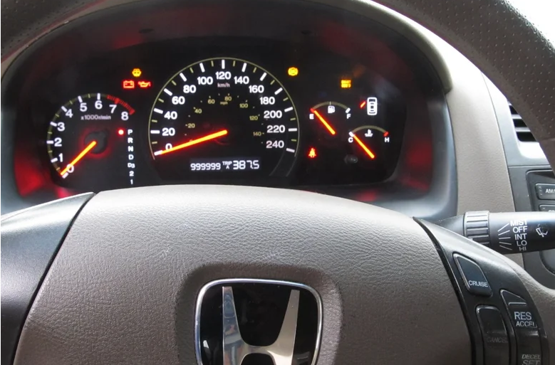
Now of course you can program anything you want. Just for fun I programmed 999,999km. The odometer dump for that looks like this.
Now you can take your million-kilometer car to the dealership and trade it in for a free brand new car!
Step 11: Additional Notes
Gauges can be calibrated by hand when the cluster is turned off. Use an OBDII scanner to determine vehicle and engine speed and coolant temperature. Calibrate the gas gauge when the gas light turns on.
The odometer does not roll over to 1 million kilometers. But the trip computer still works, as you can see here, I drove just over a kilometer to see what would happen.
Once all the gauges are closed up, it’s interesting that Honda left a hole in the back of the cluster exactly behind where the EEPROM sits, where we soldered the hookup wire. Remember though, even if you were able to solder hookup wire without taking apart the circuit board, you wouldn’t be able to write to the chip in circuit, just read from it. Just a thought.
If you want to know more about Odometer Correction Tool, please contact us sales@obd2.ltd.