This instruction show you guide on how to fault trace wires and connectorsin general.Detailed fault tracing instructions for special failure are described in Volvo Tech Tool.
Preparations:
2022 Volvo PTT Premium Tech Tool PTT 2.8.150/2.7 & 2.6 All Version Free Download
Visual checks
Check that the wires are correctly clamped and secured.
Wires clamped too tightly can cause poor contact or an open circuit.
Avoid bending the wire harness and fastening it too tight on the housing/contact.
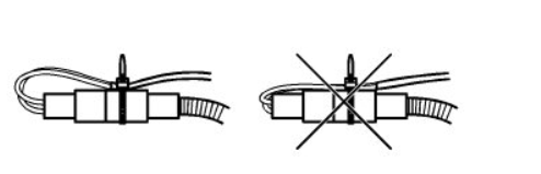
Make sure the lines are not too tightly clamped.
Hard clamped wires can cause bad contact or open circuit.

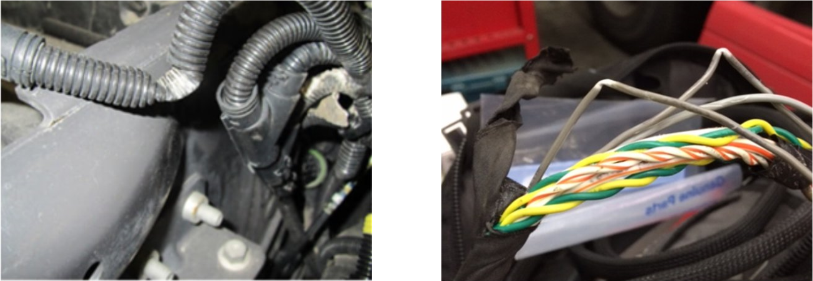
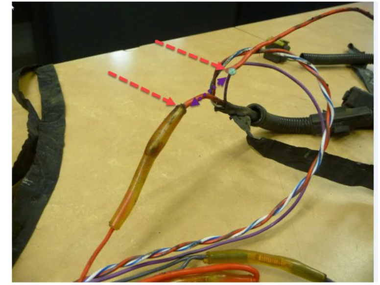
Check that the cables do not have damage from rubbing. Look specifically at places where the harness is near frame edges and consoles.
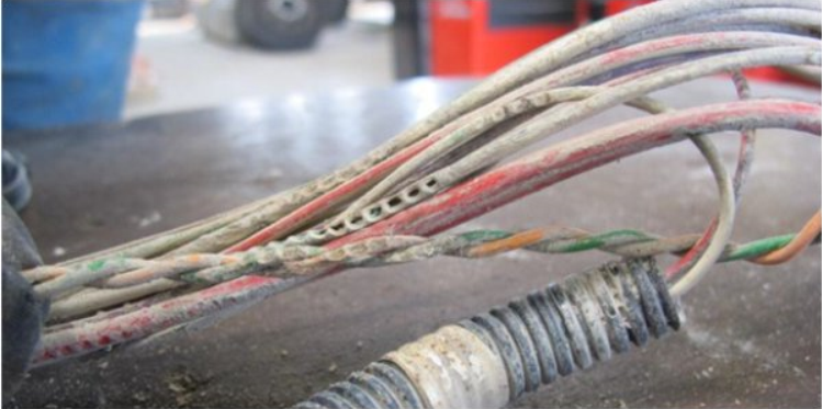
The reason for chafing damage can be:
A missing clamp
A loose clamp
Improper clamping (too long, too tight, stretched)
Connectors check
Oxidation affects the resistance of a contact which can cause permanent or intermittent interruption in the electrical circuit.
Note: Water intrusion with discolorations in Control unit connectors requires replacement of the control module
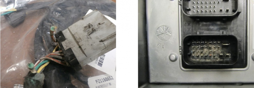
Damaged or incorrectly installed terminals
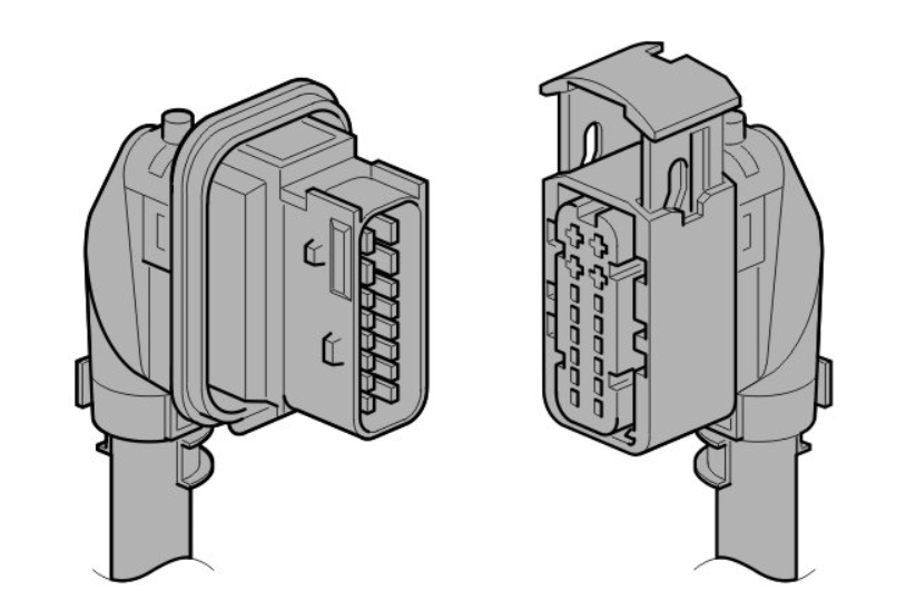
Check that the terminals are properly locked and cannot be dislodged
Check that the terminals are not bent or broken
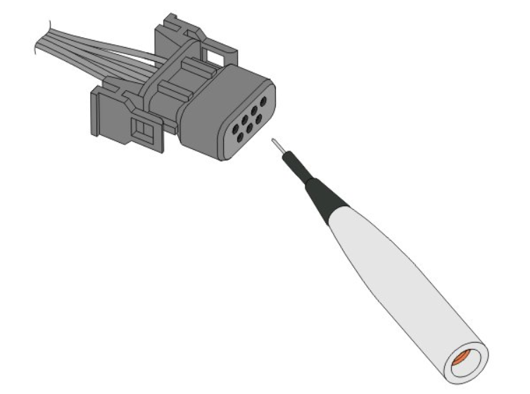
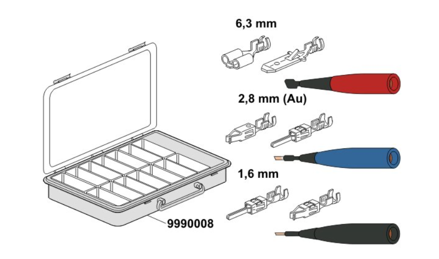
To control the elasticity of the terminals and if the terminals are locked in the connector, use the required test pins to avoid damaging the terminals.
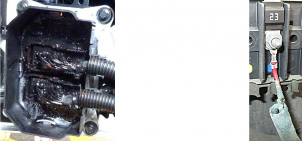
Ground connections may look good but can be corroded and/or loose which will give a poor ground connection.
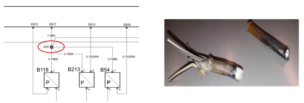
Wire splices
For chassis harnesses, corrosion in splices and where the wires connect to a splice is common. Also in common areas where the wire is connected by a y- manifold and the wire harness is not taped.
Electrical measurements
Considerations:
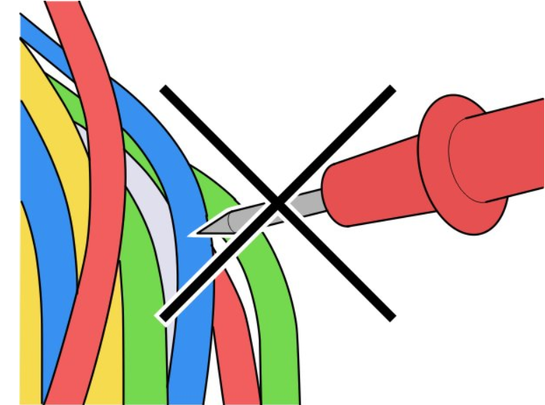
Never measure by piercing through the insulation and moisture seals in wires and connectors.
Measure a wiring harness using a multimeter and use appropriate measuring cable and measuring box.
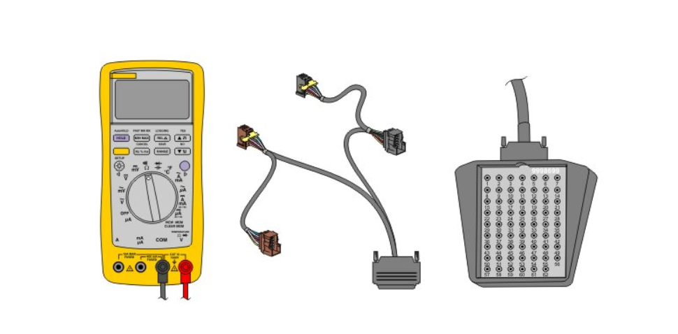
Note: When a test cable is not present, use test pins.
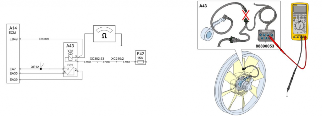
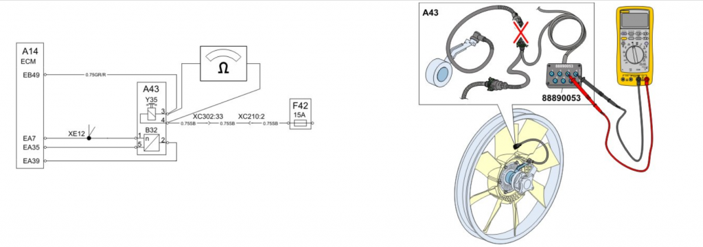
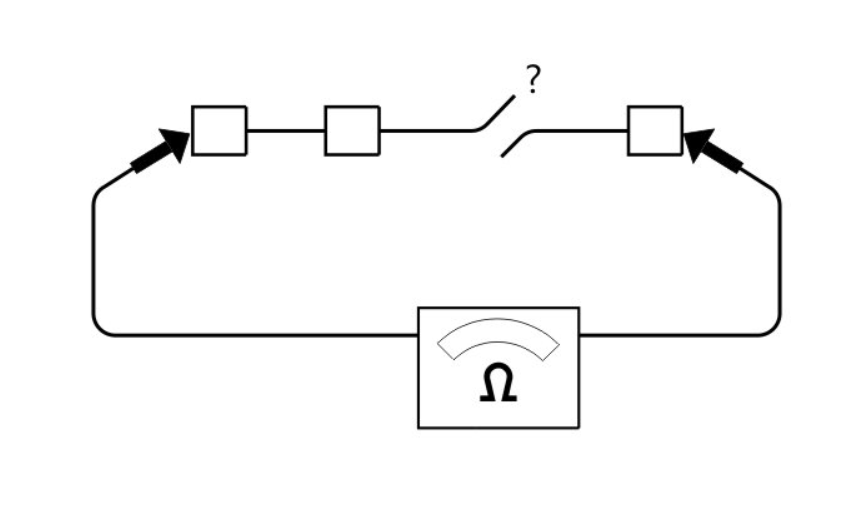
Open Circuit
Checks:
Disconnect the connectors at both ends of the wiring harness.
Measure the resistance from each end of the wiring harness.
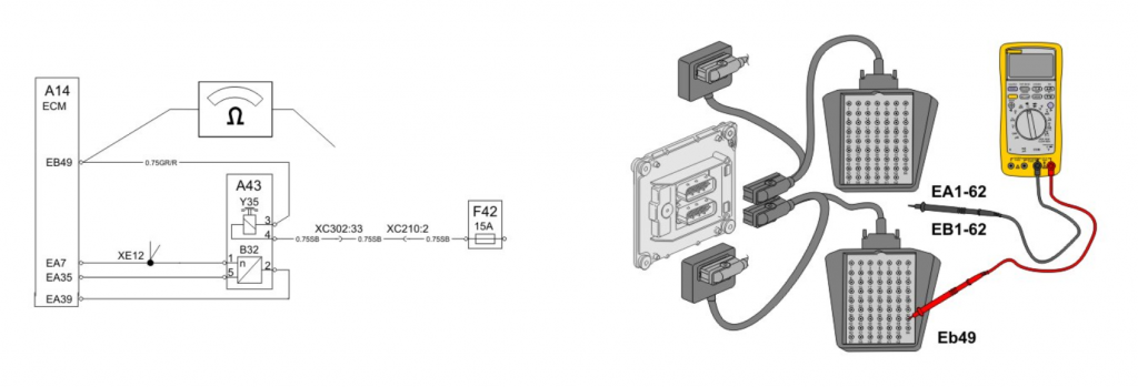
Short Circuit
Checks:
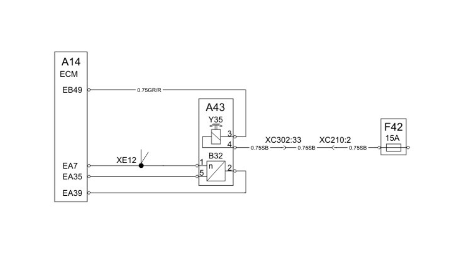
Splices in the wiring harness (XE12) affect the measurements so it is important to disconnect affected connectors to all components in the circuit. For example, it can be good to narrow the fault tracing in the engine wiring harness by disconnecting the engine interface connector from the chassis harness.