Quick Answer
PIWIS 3 remains useful for diagnosing and servicing many Porsche vehicles, but PASM calibration should never be the first response to a chassis warning. First stabilize vehicle power, inspect the suspension and sensors, verify VCI communication, save a complete fault scan and identify the actual failure. Run calibration, coding or programming only when the model-specific Porsche procedure requires that function.
Key Takeaways
-
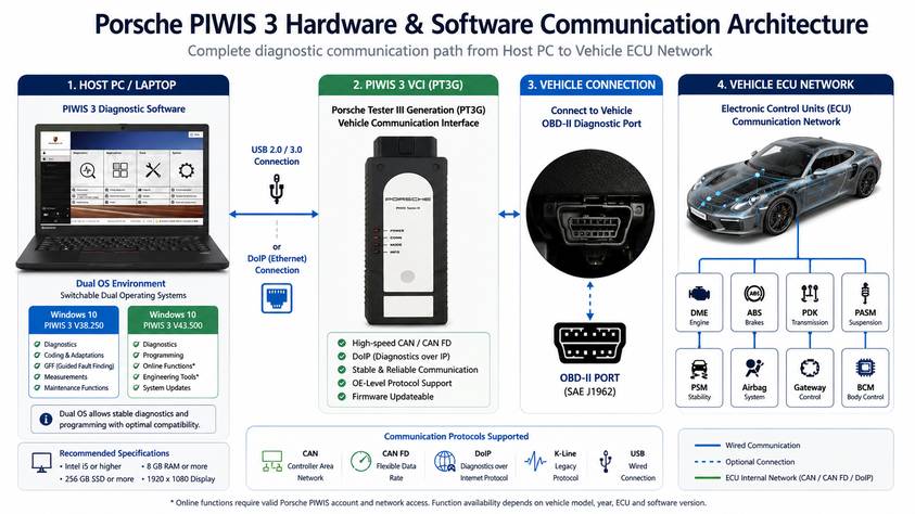
Dual-System Software Configuration:Stable PIWIS 3 builds utilize a dual OS setup—V38.200 for unrestricted offline Developer/Engineering (E) Mode coding, and V42.500+ for standard diagnostic coverage on modern models.
-
Power Supply Mandate: Programming or calibrating controllers requires an external, clean battery stabilizer supplying a steady 13.5V (minimum 50A rating) to prevent ECU bricking due to voltage drop below 12.5V.
-
Bus Protocol Separation: Older models (e.g., 986/996) rely on ISO/K-Line protocols, middle-generation platforms (e.g., 987/997, 92A) use High-Speed CAN Bus, while newer platforms (e.g., 971, 9YA, Taycan) require Diagnostics over IP (DoIP).
-
PASM Calibration Thresholds: PASM level calibration requires a level lift surface, precise wheel-center-to-fender measurements in millimeters, ambient temperatures between 15°C–25°C, and zero stored air leakage fault codes.
Scope of Application and Inapplicability
The PIWIS 3 system covers full factory diagnostic and programming functions across all legacy and modern Porsche platforms. Selecting the correct software version, VCI firmware, and connection mode determines full function availability.
Supported Vehicle Platforms & Systems
-
Sports Cars: 911 Series (996, 997, 991, 992), Boxster/Cayman (986, 987, 981, 718/982).
-
SUVs & Sedans: Cayenne (9PA/955/957, 92A/958, 9YA/93W), Macan (95B), Panamera (970, 971).
-
Electric & Hybrid: Taycan (J1), Panamera/Cayenne E-Hybrid models.
-
Protocol Support: ISO-9141-2 (K-Line), ISO-14230 (KWP2000), ISO-15765 (CAN Bus), and ISO-13400 (DoIP).
Inapplicability & Limitations
-
2024+ New Platform Transitions: Late-model vehicles (2024+) with updated SFD/Cybersecurity architectures require PIWIS 4 software and active PPN cloud authorization for certain write operations.
-
Non-Porsche OBD-II Protocols: The PIWIS 3 software interface is designed exclusively for Porsche vehicles and does not serve as a generic multi-brand OBD-II tool.
-
Security Gateway / PPN Limits: Key programming, Component Protection release, and online SVM (Software Version Management) require verified PPN dealer credentials. Offline functionality must be confirmed based on specific car model, controller version, or software version.
Symptom and Problem Definition
Technicians frequently encounter two primary categories of operational failures when using PIWIS 3: Hardware/Communication Isolation Failures and Special Function Execution Errors
Communication Isolation Failures
-
Host PC Failure to Detect VCI: The operating system displays “Device Not Recognized” or missing USB/COM ports in Windows Device Manager.
-
VCI Failure to Connect to Vehicle ECU: The VCI is powered via USB, but PIWIS 3 displays “No vehicle detected” or “Communication failure with control unit.”
Special Function Execution Errors (PASM / Coding Faults)
-
PASM Height Calibration Abort: Calibration stops mid-process, accompanied by chassis system warning messages or “Value out of range” status codes.
-
ECU Coding Rejection: Variant coding changes fail to write to the module, resulting in control unit communication errors or checksum mismatches.
Tools and Preparation Conditions
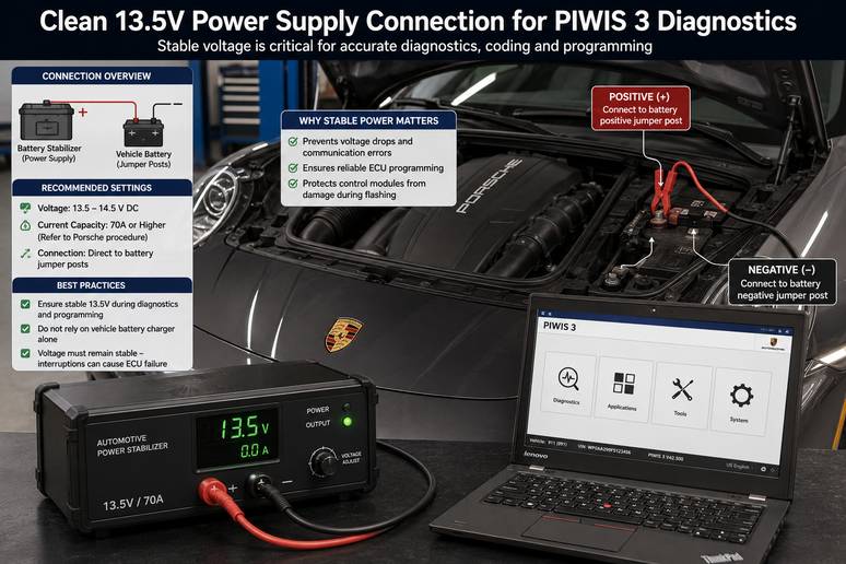
Executing diagnostic, programming, or calibration tasks with PIWIS 3 requires specific hardware, software setup, and environmental controls.
Reason Priority Table
When PIWIS 3 diagnostic communication fails or calibration routines abort, prioritize troubleshooting using this probability-based matrix:
| Failure Mode | Probable Cause | Inspection Priority | Remediation Action |
| VCI Disconnected from Host PC | Corrupted USB driver or mismatched Virtual COM port setting | High (80% of PC setup issues) | Reinstall VCI driver stack; assign fixed COM port in Device Manager. |
| No Bus Communication with Vehicle | Low vehicle system voltage (<12.5V) causing module sleep | High (70% of vehicle link issues) | Connect a clean 13.5V power stabilizer; cycle key ignition state. |
| DoIP Module Unresponsive (971/9YA) | Network adapter IP configuration mismatch on Ethernet interface | Medium (50% on DoIP models) | Set host network card to auto-DHCP or 169.254.x.x link-local subnet. |
| PASM Calibration Routine Abort | Stored DTCs in leveling control module or physical height sensor out of tolerance | High (85% of calibration failures) | Clear all DTCs in level control system; check height sensor mechanical linkages. |
| ECU Variant Coding Write Failed | Operating in standard Diagnostic (V) Mode instead of Engineering (E) Mode | Medium (60% of coding errors) | Switch to V38.200 E-Mode; verify write permissions for target ECU. |
Diagnostic & Troubleshooting Sequence
Follow this sequence to resolve tool connection issues, run diagnostic scans, perform PASM level calibrations, and execute offline ECU coding.
Phase 1: Resolving Hardware & VCI Connection Faults
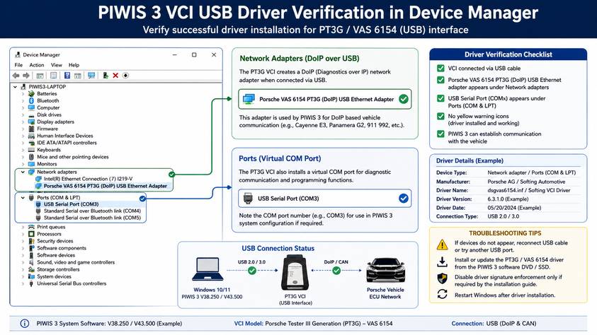
Scenario A: Host PC Does Not Detect VCI
-
Connect the VCI to the host laptop via USB 3.0.
-
Open Windows Device Manager (
devmgmt.msc). -
Check under Network Adapters or Ports (COM & LPT) for the VCI device entry.
-
If a yellow exclamation mark appears, right-click and select Update Driver, then point to the local PIWIS driver directory (
C:\Program Files\Porsche\Driversor VCI setup path). -
Ensure the VCI configuration manager software reflects an active USB connection status.
[Windows Device Manager] ──> [Ports / Network Adapters] ──> [Right Click: Update Driver] ──> [Verify Fixed COM/IP]
Scenario B: VCI Detected by PC, but Vehicle Connection Fails
-
Measure vehicle battery voltage across the jumper terminals using a digital multimeter. Ensure voltage is ≥12.5V before connecting the OBD-II port.
-
Inspect Pin 16 (12V Battery Power) and Pins 4/5 (Chassis/Signal Ground) on the vehicle OBD-II connector for correct potential.
-
Plug the VCI into the vehicle OBD-II port. Verify the power LED on the VCI illuminates solid green.
-
Launch PIWIS 3 and open Diagnostic Diagnostics Application.
-
Select the manual vehicle model selection drop-down if auto-VIN detection fails.
-
Verify whether the failure affects all control units or a single controller (e.g., DME, PSM, PASM). If all fail, check OBD DLC fuses and high-speed CAN bus connections.
Phase 2: Complete Vehicle System Scanning & Diagnostics
-
Turn ignition ON (Engine OFF). Connect the power stabilizer set to 13.5V continuous output.
-
Launch PIWIS 3 and select Diagnostics.
-
Allow the software to perform an automatic VIN read and full vehicle control unit identification scan.
-
Review the overall system tree. Note active (Red) versus historical/passive (Yellow) Diagnostic Trouble Codes (DTCs).
-
Access the target control unit (e.g., DME Engine Electronics) to inspect real-time live data parameters and execute active actuator tests to isolate faulty components.
-
Record all existing fault codes before clearing memory.
Phase 3: PASM Air Suspension Level Calibration
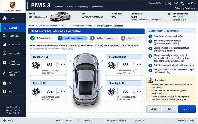
The PASM air suspension system requires recalibration after replacing suspension struts, ride height sensors, or the level control ECU.
Step-by-Step Operational Procedure:
-
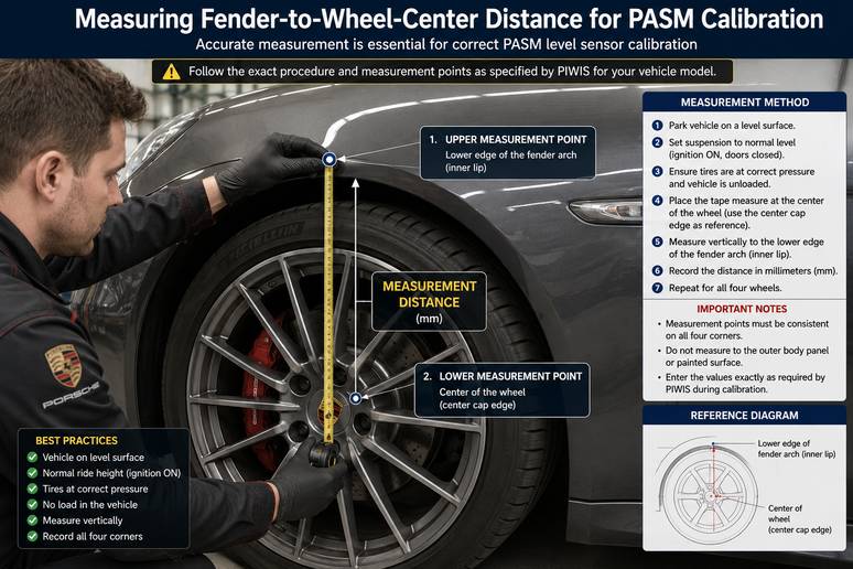
Position the vehicle on a flat, level surface or alignment rack. Ensure tire pressures match factory specs.
-
Close all vehicle doors, tailgate, and hood. Start the engine to maintain air compressor pressure, or hook up a high-amp battery stabilizer if running key-on/engine-off.
-
In PIWIS 3, navigate to PASM / Level Control Unit -> Maintenance / Repairs -> Calibration / Adjustment.
-
Confirm that zero DTCs are stored in the Level Control module. If DTCs exist, clear them before proceeding.
-
Trigger the automatic leveling sequence via PIWIS 3. The system will cycle the vehicle through normal, low, and high ride levels, returning to normal height.
-
Using a millimeter measuring tape, measure the distance from the lower edge of the wheel center cap to the lower edge of the wheel arch fender trim for all four wheels:
-
Front Left (FL)
-
Front Right (FR)
-
Rear Left (RL)
-
Rear Right (RR)
-
-
Enter the exact measured millimeter values into the PIWIS 3 input fields when prompted.
-
Execute the adaptation save command. PIWIS 3 will write the offset values to the PASM module.
-
Cycle the ignition OFF for 30 seconds, then back ON. Re-scan the PASM control unit to verify successful calibration without faults.
Phase 4: ECU Variant Coding & System Adaptation
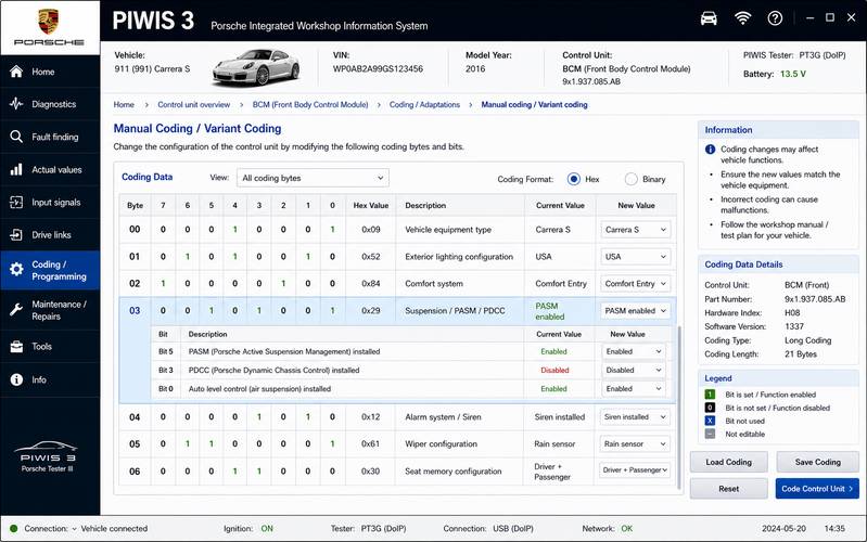
Variant coding adapts control units to vehicle-specific hardware configurations (e.g., retrofitting sports exhaust, disabling seatbelt chimes, or configuring lighting options).
-
Reboot the laptop into the V38.200 (Engineering / E-Mode) operating system partition for offline coding tasks.
-
Open PIWIS 3, select the vehicle model, and enter Mode Selection -> set mode to E (Engineering).
-
Select the target ECU (e.g.,
Front Body Control Module / BCM Front). -
Select Manual Coding Without Rules (Variant Coding).
-
Browse to the required byte/bit parameter list.
-
Modify the target values from
off/disabledtoon/enabled. -
Click Write / Execute. Wait for the confirmation message: “Coding executed successfully.”
-
Cycle ignition, return to standard V-Mode, and execute a full fault code scan to confirm no communication or coding inconsistency DTCs were generated.
Common Misjudgments and Corrective Actions
COMMON SHOP MISTAKES & CORRECTIONS
MISTAKE 1: Flashing or coding without a 13.5V continuous battery stabilizer
CORRECTION: Never use a standard trickler. Connect a dedicated 50A+ power supply.
MISTAKE 2: Attempting PASM calibration on a tilted workshop floor
CORRECTION: Verify floor flatness with a digital spirit level before starting.
MISTAKE 3: Attempting offline coding in standard Diagnostic (V) Mode
CORRECTION: Boot into V38.200 Engineering Mode to unlock variant parameters.
MISTAKE 4: Overlooking DoIP network settings on 2018+ Panamera or Cayenne
CORRECTION: Ensure the USB Ethernet adapter settings allow link-local IPs.
Stop-Operation Conditions
STOP immediately and evaluate if any of the following occur:
-
Battery system voltage drops below 12.5 Volts during programming.
-
The PIWIS 3 software displays “Communication Interrupted” or loses connection during flash writing.
-
The PASM compressor overheats or shuts down during continuous height adjustments.
-
Burning smells, unusual ECU thermal output, or persistent CAN bus system-wide communication loss occurs.
Post-Repair & Calibration Verification Checklist
Check off each item below before releasing the vehicle to service:
-
[ ] Vehicle system voltage confirmed stable at 13.5V+ throughout all procedures.
-
[ ] Complete vehicle system diagnostic scan executed; zero active (red) DTCs in any module.
-
[ ] PASM height values verified across all four wheels within factory tolerances (±2mm left-to-right variance).
-
[ ] Vehicle test driven through full chassis height modes (Comfort, Sport, Sport Plus) without dashboard warnings.
-
[ ] ECU variant coding verified by physically testing the modified vehicle function.
-
[ ] Diagnostic session log saved or printed for customer service records.
Product Selection & Hardware Compatibility
Selecting the right diagnostic hardware configuration ensures seamless workshop integration and long-term diagnostic capability.
For automotive repair facilities servicing modern Porsche platforms, hardware stability and protocol support are critical:
-
Entry-Level Diagnostic Setups: Standard VCI interfaces with single software partitions are suitable for basic DTC scanning and maintenance resets, but lack full offline coding functionality.
-
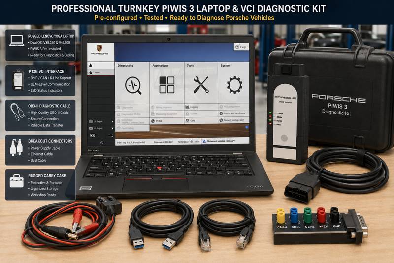
Professional Dual-Boot Diagnostic Bundles: Independent repair shops benefit from pre-configured laptop systems featuring dual operating systems (V38.200 E-Mode + V42.500+ V-Mode). These setups allow full offline variant coding on older platforms alongside comprehensive coverage for newer models.
-
Next-Generation Diagnostic Transitions: Vehicles produced from 2024 onward increasingly transition toward new security protocols. Workshops handling high volumes of late-model vehicles should evaluate future hardware upgrade paths accordingly.
Before purchasing any diagnostic kit, confirm vehicle year coverage, controller architecture, interface protocol requirements (CAN vs. DoIP), and desired coding functions with your tool provider.
If you are looking for ready-to-use factory-grade diagnostic setups, consider these verified options:
-
For standard diagnostic coverage using custom PC hardware, explore the Porsche Piwis 3 Tester III Diagnostic Tool.
-
For a turn-key professional setup with pre-configured dual-boot software, view the Porsche Piwis 3 Diagnostic Tool with Lenovo Yoga S1 Laptop.
-
For workshops expanding coverage to late-model platforms, evaluate the Piwis 4 Diagnostic Tool Plus Lenovo Yoga12 Laptop.
Frequently Asked Questions (FAQ)
What is the difference between PIWIS 3 Engineering (E) Mode and Diagnostic (V) Mode?
Diagnostic Mode (V-Mode) is the standard dealership operating interface used for fault code reading, guided troubleshooting, live data monitoring, and official service procedures. Engineering Mode (E-Mode / V38.200) unlocks developer-level variant coding, allowing technicians to modify module software parameters, adjust factory options, and perform offline ECU programming without active PPN online authorization.
Why does PASM height calibration fail midway through the process?
PASM calibration typically fails due to four reasons: stored diagnostic trouble codes in the leveling control module, a non-level floor surface, physical height sensors reading outside nominal mechanical ranges, or air system pressure drops during the routine. Always clear all DTCs and verify pneumatic system integrity before running the calibration procedure.
Can PIWIS 3 work on 2024 and newer Porsche models?
PIWIS 3 supports vehicles produced up through 2023–2024. However, newer 2024+ vehicle platforms featuring updated cybersecurity frameworks (such as SFD protection and cloud-locked ECU gateways) require the updated PIWIS 4 diagnostic platform and active PPN network authorization for online coding and module programming routines.
What battery voltage is required when performing ECU coding or diagnostics with PIWIS 3?
Vehicle voltage must remain between 13.0V and 13.5V during diagnostic sessions, and must never drop below 12.5V during active ECU flashing or coding routines. Always attach a high-capacity automotive power stabilizer rated for at least 50 Amps before performing software operations with PIWIS 3.
What is the difference between CAN Bus and DoIP connections in PIWIS 3?
Older Porsche platforms use Controller Area Network (CAN Bus) protocols for control unit communication over standard OBD-II pins. Newer platforms (such as the Panamera 971, Cayenne 9YA, and Taycan) utilize Diagnostics over Internet Protocol (DoIP), which transfers data at significantly higher speeds via high-speed Ethernet lines within the OBD interface.
Final Technical Summary & Workshop Call to Action
Mastering the Porsche PIWIS 3 diagnostic system requires balancing technical preparation, correct power management, and proper software selection. By utilizing dual-boot software environments (V38.200 for engineering coding and V42.500+ for standard diagnostics), maintaining stable 13.5V vehicle power, and adhering to strict calibration sequences, independent workshops can deliver dealer-level diagnostic services safely and efficiently.
Equip your shop with fully tested, factory-grade diagnostic hardware. Explore full diagnostic kits and dedicated laptop solutions at OBD2.LTD or contact our technical support team to verify system compatibility for your specific workshop needs.